

Sludge Storage & Pumping Solutions
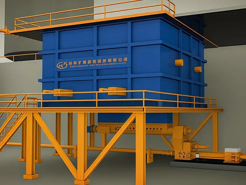
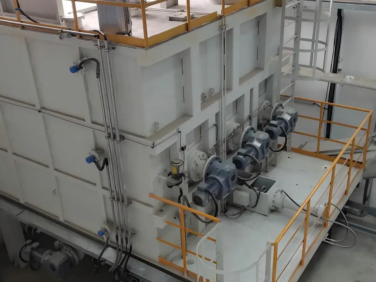
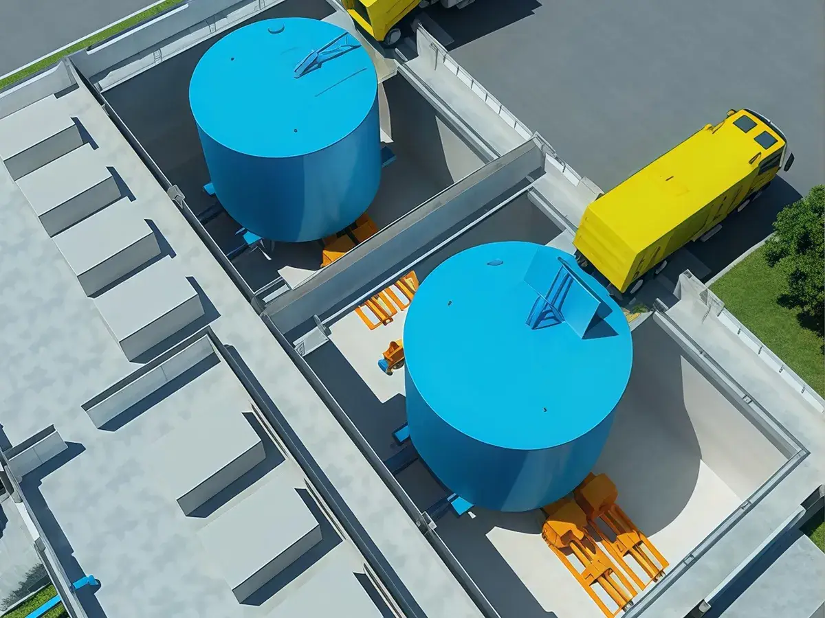
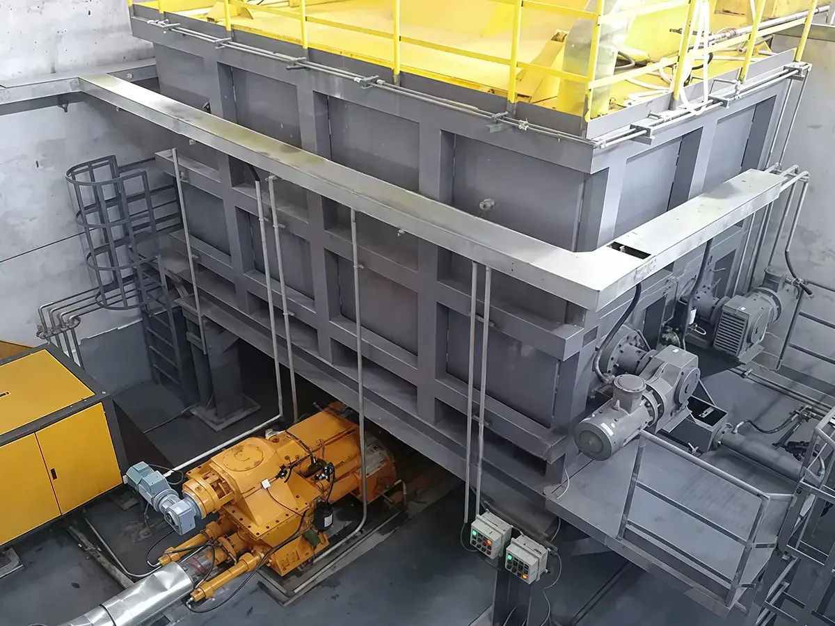
Integrated systems for storing viscous sludge, preventing bridging, and supporting stable pumping and pre-treatmentWe offer Sludge Storage & Pumping Solutions designed for thick, sticky sludge that is hard to discharge and move in a stable way. Most sludge storage and pumping systems comprise a flat-bottom sliding-frame sludge silo, then add the pumping and feeding parts needed on site, usually a plunger pump and a screw conveyor, supported by a hydraulic power unit, a debris remover, a gate valve, and a simple control system.
The sliding frame at the bottom of the silo moves back and forth, which helps break up sludge that tends to stick, form arches, or bridge over the outlet. As a result, material keeps discharging more smoothly instead of building up and blocking the flow. For storage over longer periods, the silo is built as a sealed unit and uses a corrosion-protected inner surface plus reinforced outer ribs to support the structure. A level sensor can also be added to monitor the stored volume and to make daily operation easier to manage.
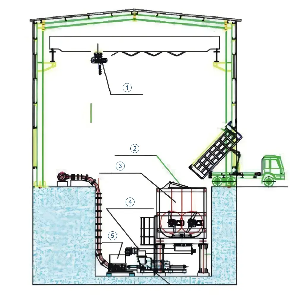
- Maintenance overhead crane
- Hydraulic access door
- Twin-shaft mixing silo
- Pre-compression screw feeder
- Hydraulic power unit (HPU) / hydraulic station
- Size reduction
- Mixing / homogenizing
- Single-Cylinder plunger pump
- Pipeline transfer
- kiln injection lance (nozzle)
- Size reduction
- screening
- coarse fraction
- dry material feeding system
- Fine fraction
- Mixing / homogenizing
- Two-Cylinder plunger pump
- Pipeline transfer
- Kiln injection lance (nozzle)
- Semi-solid, liquid, and solid waste streams
- Mixing / homogenizing
- Two-Cylinder plunger pump
- Pipeline transfer
- kiln injection lance (nozzle)
Sludge storage and pumping systems consist of a sludge storage silo, a plunger pump, a screw conveyor, a hydraulic power unit, a debris remover, a gate valve, and a control system.
| Model | Effective volume | Sliding frame qty. | HPU power | Discharge outlet qty. | Silo dimensions (L×W×H) (mm) |
| |
30 m3 | 1 | 5.5kw | 1 | 4.2×3×2.5 |
| |
40 m3 | 1 | 5.5kw | 1 | 5.5×3×2.5 |
| |
50 m3 | 1 | 5.5kw | 1 | 6×3×3 |
| |
60 m3 | 1 | 7.5kw | 1 | 7.2×3×3 |
| |
70 m3 | 1 | 7.5kw | 1 | 5×5×3 |
| |
80 m3 | 1 | 7.5kw | 1 | 5.5×5×3 |
| |
100 m3 | 1 | 11kw | 2 | 6.8×5.5×3 |
| |
120 m3 | 2 | 11kw | 2 | 7×5.5×3.2 |
| |
150 m3 | 2 | 11kw | 2 | 8×6.2×3.2 |
| |
200 m3 | 2 | 11kw | 2-4 | 8.5×8×3.2 |
| |
250 m3 | 2 | 11kw | 2-4 | 8×6.5×5 |
| |
300 m3 | 2 | 11kw | 2-4 | 12×8×3.5 |
| Model | Conveying capacity (t/h) | Motor power (kW) | Motor mounting type | Screw diameter | Inlet/outlet center distance (mm) |
| |
5 | 4 | Hollow-shaft flange-mounted | ø219-160 | 2700 |
| |
10 | 5.5 | Hollow-shaft flange-mounted | ø273-160 | 2700 |
| |
15 | 7.5 | Hollow-shaft flange-mounted | ø273-160 | 2700 |
| |
20 | 7.5 | Hollow-shaft flange-mounted | ø325-250 | 2700 |
| |
30 | 11 | Hollow-shaft flange-mounted | ø377-250 | 3000 |
| |
40 | 15kw | Hollow-shaft flange-mounted | ø426-250 | 3000 |